01 / Presence sensors
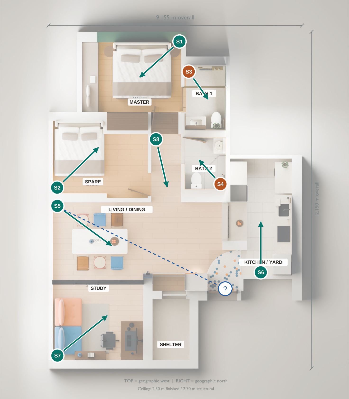
- S1Master bedroom
Plan-top-right corner, facing diagonally toward the bed. Test the bed and doorway; avoid curtain interference.
- S2Spare bedroom
Plan-bottom-left corner, facing into the room. Keep clear of curtains and test with the door closed.
- S3Master bathroom / Bath 1
Plan-top-left shower region toward the room. This wet-area candidate needs supplier and installer review; test across the shower glass.
- S4Common bathroom / Bath 2
Plan-bottom-right shower region toward the interior. Keep away from the shower jet; final mounting depends on wet-area suitability.
- S5Living / dining + entrance
Plan-top-left beneath the spare room, aiming across dining. The shelter corner may hide the threshold; the entrance assignment is provisional.
- S6Kitchen / yard · entrance end
At the kitchen entrance end, on an exposed wall or suitable bracket with a clear view along the aisle. Aim plan-up toward the yard; this is a direction on the drawing, not a tilt toward the ceiling. Confirm the support, mounting height and coverage on site.
- S7Study
Plan-bottom-left toward the room and desk. Test around the sofa, bookshelf and sliding glass.
- S8Bedroom corridor
Master end, on the corridor-side wall or bracket, aiming plan-down. Keep clear of the revised master door swing.
Use wall / suitable bracket mounting for multi-zone presence. Conceal wiring through available coordinated routes; keep the radar face exposed. No kitchen renovation or new false ceiling is planned: S6’s power/cable route also remains to be confirmed. Ceiling fall-detection mode is not a substitute for this arrangement. Select the height by room trial with the logo level. The old sketch’s 1.6–1.8 m is not an approved mounting rule.
Provide continuous USB power, an accessible supply and serviceable connections. Check 2.4 GHz Wi-Fi at every location.
Bathroom detailing and the trial checklist
Aqara identifies the FP2 as IPX5 and says the adapter and wall outlet must be waterproof for humid use. This does not certify the complete exposed USB connection or a shower-zone installation. Have the supplier and installer detail the actual sensor, connector, supply location and protection; avoid direct spray and keep the face exposed. Reposition S3 / S4 if suitability cannot be established.
Test bedroom and entrance doors open / closed; study sliding glass open / closed; shower glass open / closed; a shower occupant and running water without an occupant. Check bed, desk, WC, basin, corridor and entrance occupancy, plus curtains, AC and fans. Configure room edges and interference areas after the trial.
Official guidance checked 6 Sep 2026: FP2 productUser manualInstallation FAQ
02 / Five ceiling speakers + one tabletop provision
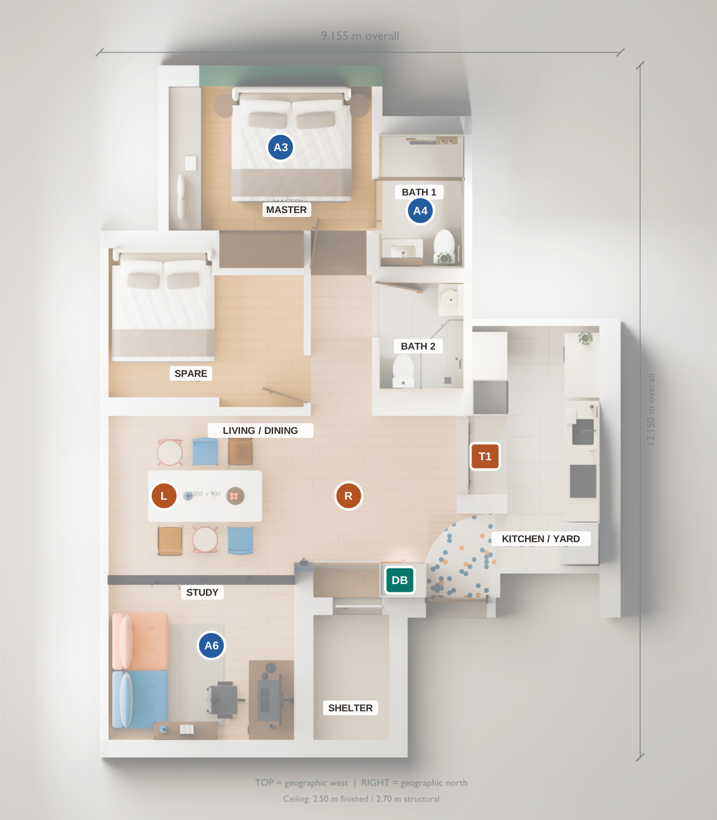
- LLiving / dining · left channel
One ceiling speaker on the plan-left side of the current dining/shared arrangement.
- RLiving / dining · right channel
One ceiling speaker toward the shared aisle. Confirm listening orientation and clear the dining pendant.
- A3Master bedroom
One single stereo DVC speaker; both left and right channels.
- A4Master bathroom / Bath 1
One single stereo DVC speaker proposed on the dry side; supplier to confirm bathroom suitability.
- A6Study
One single stereo DVC speaker for the current desk/lounge room, labelled FLEX in the old sketch.
Proposed on the existing left-hand surface inside the kitchen, near the power supply confirmed by the user. The exact outlet is not surveyed; the symbol indicates an approximate surface position. This is separate from the dining table outside. Audio output only; no microphone or purchased product assumed. Connection, amplification and power remain TBD, with no new kitchen false-ceiling work.
Six audio positions across five areas: five ceiling speakers + one tabletop provision. No speakers in the spare bedroom, common bathroom or shelter. The kitchen ceiling speaker and its dedicated wiring provision are removed because no kitchen renovation or false-ceiling work is planned. The living pair follows the current dining layout rather than the old sofa arrangement.
Living R → rack R channel
A3, A4, A6 → separate room home-runs, each carrying L + R channel pairs
Each DVC speaker needs four conductors for its two channels. Keep each room independent, without a room-to-room daisy chain. Label both ends. Supplier to choose cable type / gauge from the actual length and equipment load; amplifier model and routing remain open.
The model has a 2.50 m finished and 2.70 m structural ceiling. The nominal 200 mm void is not verified usable installation depth. Survey services, framing, lighting, AC and glass tracks. Confirm the selected speaker’s cut-out, depth, back enclosure, clearances, bathroom rating and service access before closing the ceiling.
03 / Furniture-height conversation points
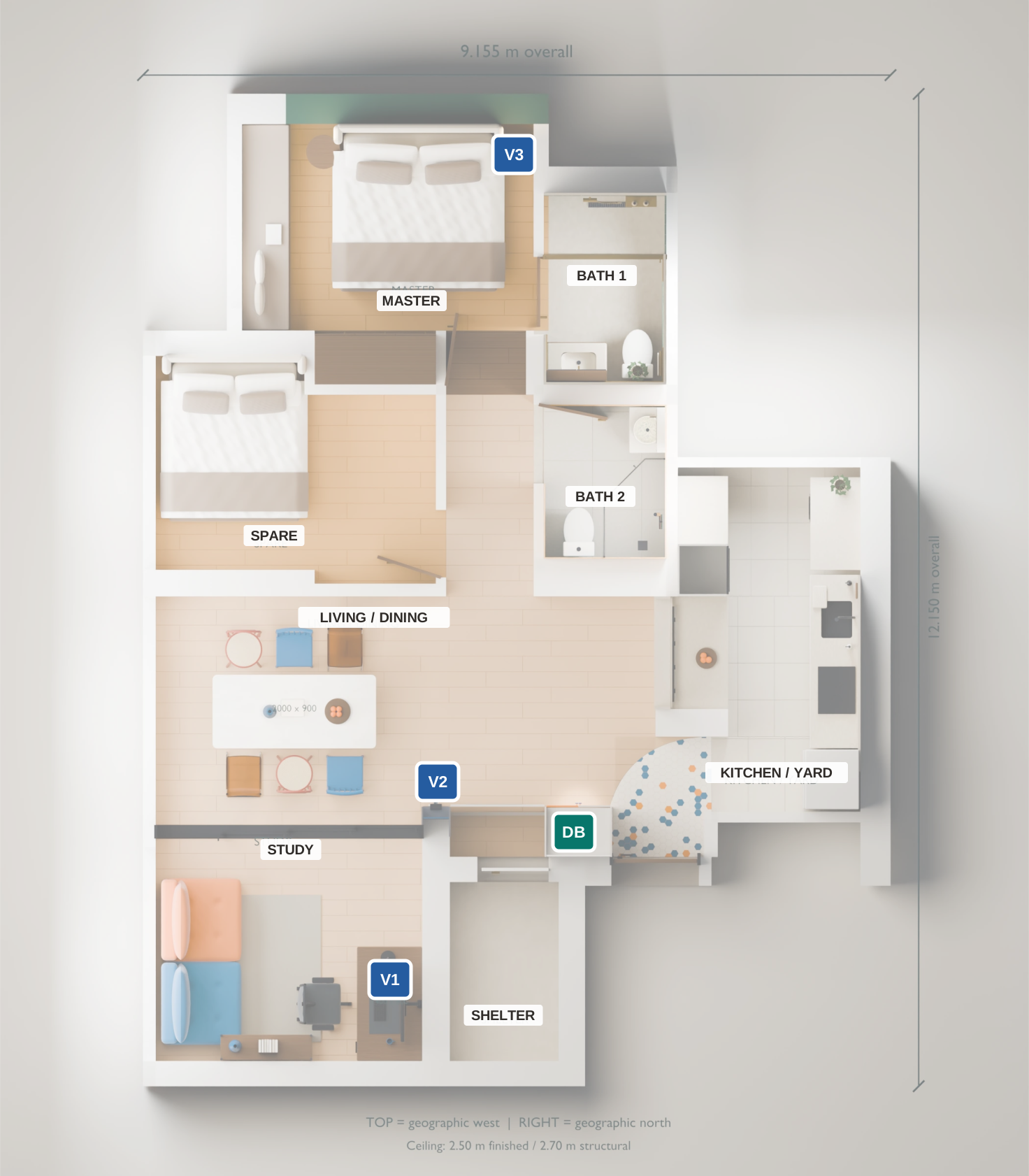
- V1Study · prototype first
Accessible desk position. Leave the microphone clear and allow cable slack for the motorised desk and monitor arm.
- V2Living / dining
Provisional low console or shelf by the study-side wall. Agree this furniture provision with the ID.
- V3Master bedroom
Accessible bedside surface, clear of curtains and obstructions.
Reserve concealed power and data pathways to these furniture locations, with accessible terminations. The mic array and small local speaker remain within reach. Hardware, power method and final cable specifications are unselected.
Validate the study first
Prototype natural conversation and interruption handling with music and AC on and the sliding glass closed. Check pickup and echo at the desk and lounge before repeating the arrangement in living and master.
Start with local conversation output
The small local speaker is the initial AI voice output. Ceiling speakers are planned for music and announcements. Whether they carry AI conversation later is deliberately undecided.
What future ceiling voice routing needs
Prototype the amplifier and audio route for latency, music ducking and a synchronized playback reference for acoustic echo cancellation. A generic smart amplifier does not establish those capabilities. An owner-controlled central AI system can connect to optional Home Assistant automation later; this plan selects no ecosystem and builds no software.
Concealed routes, accessible endpoints
Coordinate pathways from the entrance equipment bay through the ceiling and down walls or joinery. Preserve replacement access and cable separation. The symbols do not establish construction-approved routes.
04 / Wireless · ceiling access points
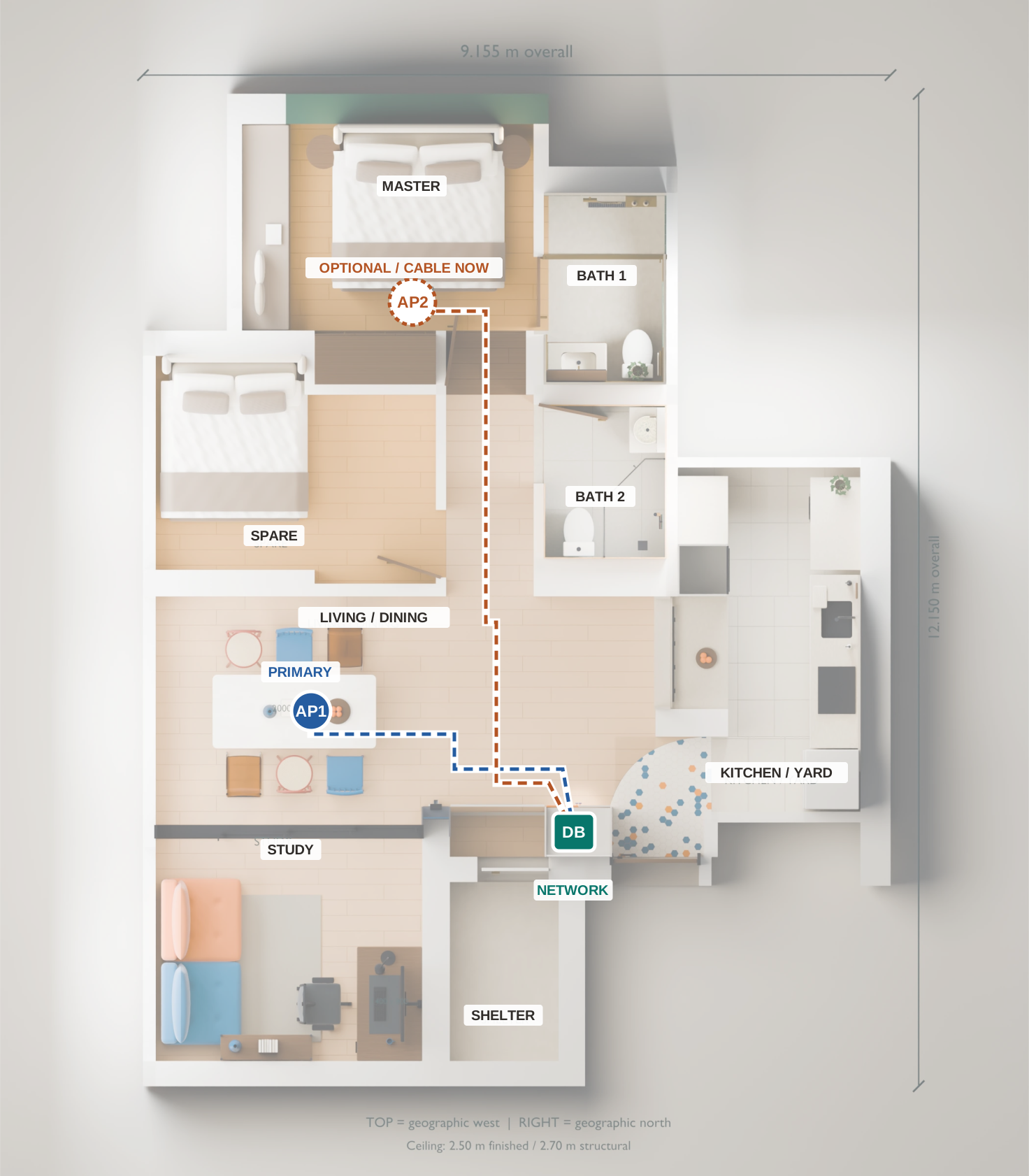
- AP1Living / dining · primary ceiling AP
Above the dining table. Coordinate the final ceiling point with the pendant and L / R speakers, then trial coverage with the chosen AP.
- AP2Master bedroom · optional future ceiling AP
Provide the separate Ethernet cable now. Install an AP later only if coverage testing shows it is useful. Coordinate this point with master speaker A3 and ceiling services.
- DBEntrance cupboard · network equipment
User-described UniFi Fiber Gateway. Exact model and ports are not verified. Preserve access and coordinate network power equipment with amplifier and computing space.
E2 · DB network equipment → optional AP2 master ceiling provision
Run each cable back to the DB network equipment; do not daisy-chain AP1 to AP2. Label both ends and test each run. Leave the unused master end safely terminated and accessible at a coordinated ceiling outlet or service point for later fitting.
Test the primary AP using the actual devices around the home, with bedroom doors and study glass both open and closed. Check the master, study, kitchen and all sensor locations. The floorplan and cable lines do not establish guaranteed wireless coverage or prove that two APs are required.
Confirm compatible power equipment
The gateway’s exact model and the AP models remain unverified or unselected. Do not assume the gateway supplies PoE or Wi-Fi. Check its LAN connections and the chosen AP’s power requirements; a compatible PoE switch, injector or other supported power provision depends on those products. Allow accessible power, space and ventilation in the DB equipment bay.
No fixed cable category, switch, injector, AP model or network configuration is specified here. Use the selected AP’s mounting kit and coordinate ceiling fixings, services and maintenance access. No kitchen false-ceiling work is added.
Official guidance checked 6 Sep 2026: Ubiquiti PoE overviewAP placement and coverage testingCeiling mounts
Resolve together before the ceiling closes.
01 / Survey + trial
Confirm usable ceiling space and services. Trial all eight sensors, including S6 from the kitchen entrance toward the yard, bathroom glass and the entrance blind spot. Prototype study voice with the room in use.
02 / Coordinate the equipment bay
Add amplifier rack provision alongside the UniFi fibre gateway, Raspberry Pi and possible Mac mini. Confirm DB access, outlets, equipment clearances, shelf loading, cable management and ventilation from actual heat loads.
03 / Agree + record
Select products and furniture, mark measured points and cable routes with the ID, then label, photograph and test every run before closure. The entrance vent design does not prove sufficient cooling.